Smart Mirror

I’m building a smart mirror for my refurbished bathroom. Starting with a damaged LED mirror as the base I already have half of the underlying infrastructure in place. The LED mirror was already wired safely onto the wall and the insulated steel frame had drivers, transformers and other electrical components inside. Since the mirror itself was damaged when I removed it to store during the bathroom refurbishment, I needed a new partly silvered glass and I ordered this in the excellent Mirropane™ Chrome Spy having selected this from the sample pack sent by Brigla-Therm.

Removing the old broken mirror from the frame wasn’t easy! In fact, it was downright scary slowly prising off shards of glass from their glue and I did it very, very slowly. Once removed, I cleaned the old frame and reattached the new mirror glass using bathroom silicone sealant. Light showed through from the overlapped areas behind the white tiled wall so I covered the overlapped sides using black tape.

I chose a VA type of monitor after looking at the discussions on the MagicMirror forum. Apparently these show better contrasts than TN or IPS types, although their response times are slower and less suited to gaming. That’s fine by me – I’m not planning to run anything fast moving on this display as the primary things will be static text and graphics.

The software is relatively simple; I saw one video where the builder said that ‘maintaining JSON was hard’. As a software developer I find it relatively easy so the approach I have gone for is to run the MagicMirror (MM) server remotely in a virtual container and use a browser on a very small client (Raspberry Pi Zero W) to boot and display a single page in full screen mode. I like and admire DakBoard but firstly it is a subscription instead of a one-off cost, and I feel it is also more geared towards the commercial smart mirror provider with billing plans for your remote clients.

I’d also like to control the monitor’s buttons using the GPIO from the RPi but I am uncertain at the moment how to do this. I’d also like to physically turn off the monitor back light when not in use but again not sure yet how this would work. Relays seem an obvious choice.

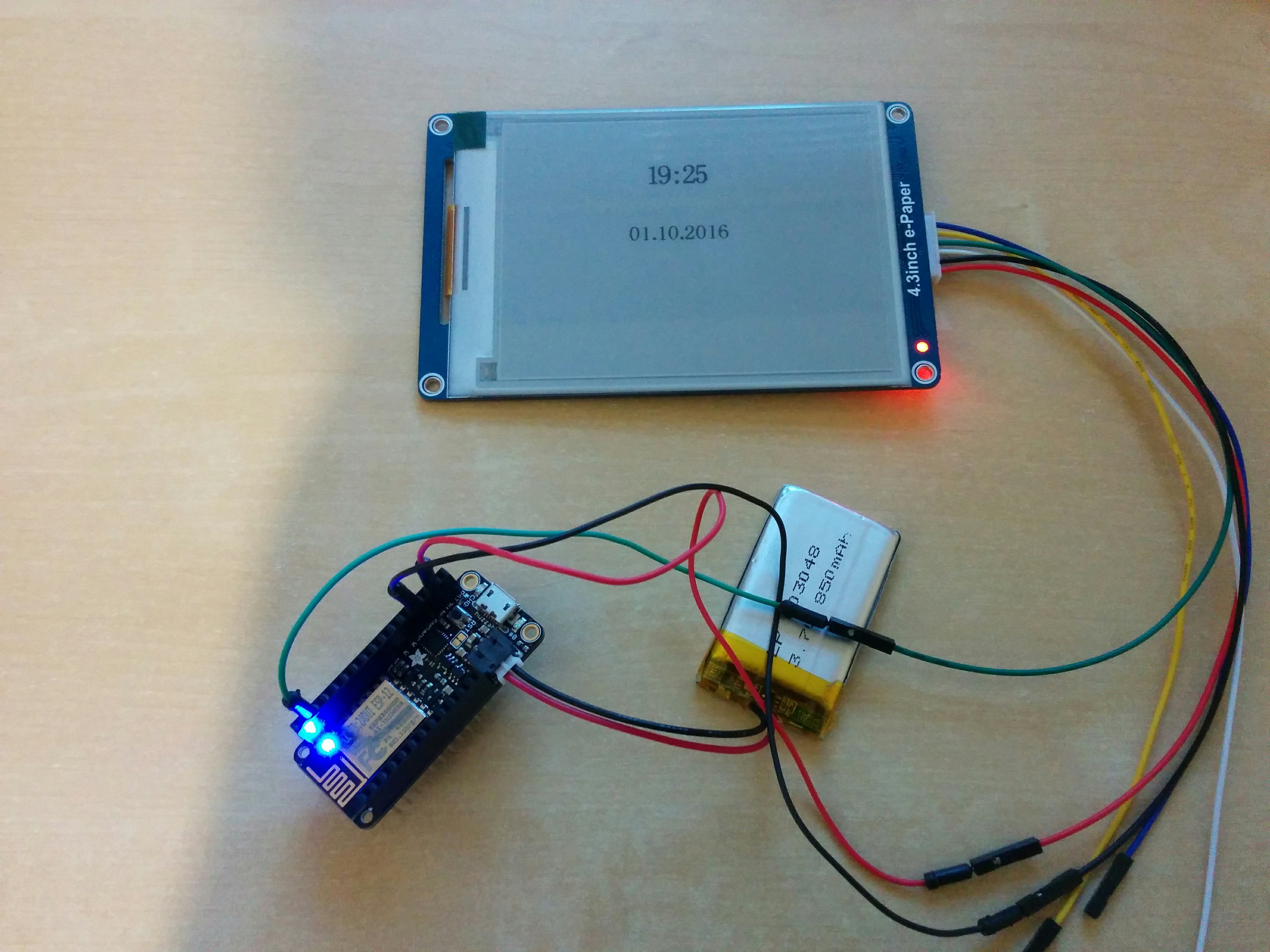
Power was a challenge as the space behind the mirror is limited particularly in the thickness dimension. Instead of the hulking wall-warts I have decided to build a small soldered breadboard with miniature power supplies to convert from the standard 230V delivered to the mirror into the 12V and 5V needed by the monitor and RPi.

Blutack and masking tape

I’ve started masking the base PCB of my WiFi doorbell and I am using both masking tape and Blutack. I discovered the Blutack while going through my stationery drawer looking for something similar to the latex masking fluid which is used in real electronic waterproofing. I had thought of using an eraser which would be soft and pressed onto the micro-USB port would mostly seal against the conformal spray. The Blutack is now my best friend for masking, even if the spray dissolves it some and leaves it sticky – but the easiest way to remove Blutack is using more Blutack, which worked very well on the PCB board.

I decided to leave the camera alone as it was already in a unit, and previous experience has taught me that getting near lenses with any type of fluid or compound invariably means that you leave smears, no matter how careful. As it is a single unit I’ll seal around its seating and hope that that helps prevent major water ingress into the rest of the mechanism. If the video feed fails, I’ll know better next time!

The speaker at the bottom is also hard to waterproof: cover it in conformal fluid or seal it in somehow would mean that it likely could not be heard, and similarly for the microphone which needs to vibrate to detect speaking. I’ll simply seal around the edges of those components and hope that their internals are okay with a little moisture.

Miniature speaker at bottom of unit

The door-press button is difficult, as it needs to move to trigger the micro-switch, but isn’t sealed around its edge – I assume that rain against the front of the unit seeps through capillary action around the edges and into the major internal space, and thence via condensation onto other surfaces. That’s bad, as it possibly means I cannot seal one of the areas of major ingress.

Press button is … difficult

Experimenting is fun, so I am going to try a thin film of plastic wrap (sometimes called ‘cling film’ here – other names elsewhere!) glued to the rear of the face plate to see if that works. The plastic film should bend enough to allow depressing the micro-switch, but the real challenge will be getting it sealed against the back of the face plate. I will try a rim of silicone sealant to which I will press a square of plastic film.

Overall the task took me the whole day. While that seems a little crazy (and you may prefer watching box sets on television), I saw it as a learning exercise and bit of a challenge! I’ve thought through how to waterproof a very difficult piece of equipment and although the proof that it’s successful still remains, I am overall pleased with the result and would attempt something similar with greater skill.

The doorbell does work now and I have tested it both via pressing the push button and the mobile app. Bring on the rain!

Waterproofing electronics

I’ve been interested in getting a WiFi doorbell for my house. Having looked at the issues surrounding the two market-leading brands, decided to go the cheaper route and purchased a no-name brand from China.

The doorbell and separate chime are excellent, but are not waterproof.

I experienced this after having had the doorbell working for a week or so – England is anything but dry and before Christmas a downpour lashed our front elevation for around 18 hours, thoroughly wetting the outside of the unit. While the camera still worked and I could connect to it from my phone app, I did not suspect that water had entered the compartment. When it did occur to me was after one door press by the post delivery worker that left a lingering ‘ding dong’ in the air after it should have stopped.

The next day the lingering ‘ding dong’ did not stop at all and I had to remove power from the chime unit. I opened the unit and saw moisture inside and dried it out, but realised several days later that I could not connect to the unit from the mobile app and so have taken it off the wall to fully waterproof it. Thankfully the ringing had stopped but I worried that it could re-occur in the middle of the night or while we were away.

Components of the video doorbell

I will use electronic conformal liquid in a spray form to coat the PCB and internals, and will try to either glue non-moving parts in place with silicone sealant as well as putting a bead around the external rim of the back-plate. My challenge is that there is several holes where ingress is needed for the microphone and the speaker! How to waterproof those? And the press button will still have to move inwards to depress the micro-switch and if glued solid it could not do this.

Weather calendar: Feather Huzzah

The Adafruit Feather range is a very nice set of development boards from the NYC company. They are a good form factor (approx. 5x2cm) and stack using appropriate headers. I particularly like the Feather Huzzah and initially went for these in a big way as they fulfil a number of criteria:

  • they can run MicroPython,
  • the processor boards are wifi-enabled,
  • and some added benefits like lots of additional addons (RTC, OLED, 7-segment displays) plus great tutorials on their web site.

Initial and ongoing experience proved that they were very easy to work with, and they worked as expected. However, the ESP8266 wifi-enabled board does not go into a really low-power mode, consuming about ~70mA normally and the deepsleep mode requires manual intervention. That will most likely mean that I can’t use it longer term for the driver on the display, but it will prove useful as a learning exercise on the way down the power ladder.

Using Arduino IDE

I initially started by loading MicroPython onto the board using the esptool flasher, but ran into an issue that I could not seem to find the correct pinout for the Tx/Rx. Using the ones marked on the board interferes with the USB – serial controller and you see spurious things on the link. So I backed off and re-flashed it with the Arduino IDE and a neat little bit of example clock code which works well, proving that the Tx pin works at least, and the battery powered Feather Huzzah can indeed drive the e-ink display.

img_20161001_182615

MicroPython

However, using micropython proves more difficult, as I cannot seem to find the correct Tx pin for UART 1.  Having flashed the 1.8.4 code level onto it using the instructions I initially tested UART(0), but as this is connected to the USB-serial chip you get all the USB traffic on those pins and so I looked to the write-only UART(1). I could not find which physical pin this was attached to even after trying all the pins one by one.

Weather calendar, part deux!

Whilst some of my systems have worked, some have not. First up, I have no problem in getting a display on the e-ink displays which I have (a Pervasive Displays, Waveshare) using their demo programs and using either a USB connection or an Arduino.

Arduino

Simplest is the Arduino code and communicating to this via a USB connection, using the Arduino GUI on a Linux machine. This works!

PC

Second easiest is talking to the display directly using a UART connection from a PC, such as the CP2102 chip and driving the display via the USB cable:

  • Using a Python library works well.
  • Using the C code supplied by Waveshare themselves as a library – not tried but I assume it would work like the Python code.

Adafruit Feather Huzzah

  • running MicroPython did not work and gave a memory error
  • running the NodeMCU?

Eventually the memory error helped realised that I may have been approaching it like it was a large system, is there a way I can keep the memory requirements much lower and get the display working? The Huzzah is a good system, although it is a little power-hungry for my liking.

WiPy

Using a WiPy running MicroPython also did not work. I was a little disappointed with this as I think the system is a good one.

Photon

I’ve one of the little Particle.io systems and have played with it, but as the programming was not in Python not taken it further. It could be a possibility but I want to push the MicroPython boards to see if one can handle what I want to accomplish.

Pyboard

I have one of the v1.0 Pyboards from the Kickstarter campaign, and got this working driving the Pervasive Displays display. Mostly because someone else wrote the code and gave a great walkthrough for the wiring and soldering needed.

ESP8266

I’ve ordered a ‘raw’ ESP8266 as one Youtube video shows that working okay as an endpoint, with the Python code running on a backend laptop. I can get one of my small SBCs to do the driving. More on this later…

TXB0108

Logic voltages have changed over the years since the Arduino first came out, and modern chips are largely based around the 3.3V compared with the 5V of the early Arduino systems. Of course this varies and some are 1.8V and so on. I wondered if I were driving the display with the wrong voltage. The Waveshare site claims that the display can handle 3.3-5V okay, although I note that they say you feed it 5V when using their demo program to talk to a PC.

I tried to use a level shifting chip – the TXB0108 – which will either up-shift or down-shift the logic levels on the control lines (and not the voltage! – that I had to realise, so you still must supply 5V somehow). Whilst the results were tantalising, they were inconsistent when only supplying 3.3V to the display as often the updates would not come through and the screen looked ‘broken’.  Feeding 5V worked perfectly. Learning about level-shifting was fun, and may come in handy for later projects, but I’ve assumed that I need a 5v feed to the Waveshare display with 3.3V logic levels on the TX/RX and

Weather calendar

I have been thinking and tinkering around creating a home weather calendar. The background is that we have a variety of hand-held devices such as mobile phones, PCs and tablets as well as a reasonable in-house network, both wired and wireless.  I’ve also a number of local sensors such as weather stations and temperature sensors, and some level of automation with programmable lighting. I’d like to create a weather calendar to display the local weather forecast, plus upcoming calendar entries from our joint shared Google calendars.

Some simple requirements:

  1. High contrast display that can run from battery – LCD or e-ink.
  2. Low-powered system that can run a long time from a battery.
  3. Wifi connected so that I can work on it remotely.
  4. Preferably coded in Python as I am happiest working in that language.
  5. Preferably all local to the display.

To do this I am going to assemble some components:

  • e-ink displays
  • Embedded systems
  • Single-board computers

… of which I have a couple of e-ink displays (Pervasive Displays and Waveshare models), a handful of embedded systems (Pyboard, Photon, Feather Huzzah, WiPy) and any number of SBCs (Raspberry Pi, Beaglebone Black, Odroid, Arduino).

I rejected powering this off a SBC like the Raspberry Pi as the power requirements for those are bad as even the Pi Zero will only run for less than a day with AA batteries! The vast differences between those chips that run a full Linux stack versus the embedded world that have negligible power draw on sleep mode. In addition a lot of those embedded systems are wifi-connected, and wifi itself is power hungry and needs careful sleep modes.